Introduction
Two years ago, Microsoft released a new feature as a part of the Insiders build 18305 – Windows Sandbox.
This sandbox has some useful specifications:
- Integrated part of Windows 10 (Pro/Enterprise).
- Runs on top of Hyper-V virtualization.
- Pristine and disposable – Starts clean on each run and has no persistent state.
- Configurable through a configuration file that has a dedicated format (WSB format). You can configure networking, vGPU, mapped folders, an automated script to run at user login, and many other options.
- The deployment is based on Windows Containers technology.
Judging by the accompanying technical blog post, we can say that Microsoft achieved a major technical milestone. The resulting sandbox presents the best of both worlds: on the one hand, the sandbox is based on Hyper-V technology, which means it inherits Hyper-V's strict virtualization security. On the other hand, the sandbox contains several features which allow sharing resources with the host machine to reduce CPU and memory consumption.
One of the interesting features is of particular importance, and we will elaborate on it here.
Dynamically Generated Image
The guest disk and filesystem are created dynamically, and are implemented using files in the host filesystem.
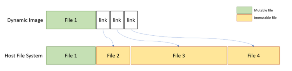
Figure 1 – Dynamically generated image (from Microsoft official documentation).
We decided to dig deeper into this technology for several reasons.
- Lack of documentation on its internal technicalities, both official and community-based. While it combines two widely documented technologies (Windows Containers and Hyper-V), we are still missing on how it all works together. For example, the technical blog refers to the Windows Containers technology, but in the official documentation, the creation and management of Windows Containers is done using the Docker utility for Windows, which isn't used in Windows Sandbox.
- Unfortunately, Microsoft does not allow any customization to the sandbox other than tweaking the WSB file. This means we can't install any program that requires a reboot, or create our own base image for the sandbox.
In this article, we break down several of the components, execution flow, driver support, and the implementation design of the dynamic image feature. We show that several internal technologies are involved, such as NTFS custom reparse tag, VHDx layering, container configuration for proper isolation, virtual storage drivers, vSMB over VMBus, and more. We also create a custom FLARE VM sandbox for malware analysis purposes, whose startup time is just 10 seconds.
General Components
The complex ecosystem of Hyper-V and its modules has already been researched extensively. Several vulnerabilities were found, such as the next VmSwitch RCE which can cause a full guest-to-host escape. A few years ago, Microsoft introduced Windows Containers (mainly for servers), a feature which allowed running Docker natively on Windows to ease software deployment.
Both these technologies were also introduced to the Windows 10 endpoint platform in the form of two components: WDAG (Windows Defender Application Guard), and most recently, Windows Sandbox. Lately, WDAG and another exciting feature for Office isolation were combined as MDAG – Microsoft Defender Application Guard.
In the POC2018 conference, Yunhai Zhang had a presentation where he dived into the WDAG architecture and internals. As we demonstrate, Windows Sandbox shares the same technologies for its underlying implementation.
The sandbox can be divided into three components: two services – CmService.dll and vmcompute.exe – and the created worker process, vmwp.exe.
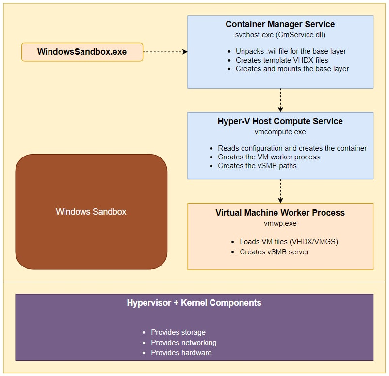
Figure 2 – Windows Sandbox general components.
Preparing the Sandbox
Behind every Hyper-V based VM there is a VHDx file, a virtual disk which is used by the machine. To understand how the disk is created, we looked at the working folder of an actively running sandbox: %PROGRAMDATA%\Microsoft\Windows\Containers. Surprisingly, we found more than 8 VHDx files.
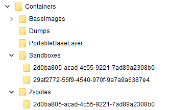
Figure 3 – Working folder structure.
We can track the main VHDx file by its dynamic size at the next path – Sandboxes\29af2772-55f9-4540-970f-9a7a9a6387e4\sandbox.vhdx, where the GUID is randomly generated on each sandbox run.
When we manually mount the VHDx file, we see that most of its filesystem is missing (this phenomenon is also visible in Zhang's WDAG research, mentioned previously).
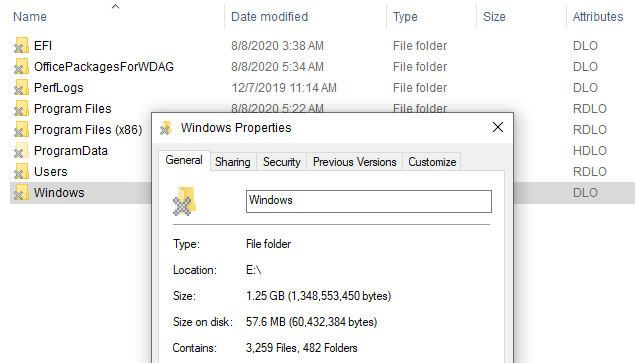
Figure 4 – Mounted sandbox VHDx.
We can immediately observe the "X" sign on the folder icon. If we turn on the "attributes" column in File Explorer, we can see two unusual NTFS attributes. These are explained here:
O – Offline
L – Reparse Point
Reparse Point is an extension to NTFS which allows it to create a "link" to another path. It also plays a role in other features, such as volume mounting. In our case, it makes sense that this feature is used as most of the files aren't "physically" present in the VHDx file.
To understand where the reparse points to and what's there, we delve deeper into the NTFS structure.
Parsing MFT Record
The Master File Table (MFT) stores the information required to retrieve files from an NTFS partition. A file may have one or more MFT records, and can contain one or more attributes. We can run the popular forensic tool, Volatility, with the mftparser option to parse all MFT records in the underlying file system. This can be done using the following command line:
volatility.exe -f sandbox.vhdx mftparser --output=body -D output --output-file=sandbox.body
When we search the kernel32.dll (a sample system file) record in the output, we encounter the following text:
We can see similar reparse ("S") and offline ("o") attributes as we did earlier, but Volatility doesn't give us any additional information. We can use the offset of the MFT record, 0x3538c00, to launch our own manual parse.
We used the next NTFS documentation for the parsing process. We do not provide a full specification of the MFT format, but to put it simply, MFT records contain a variable number of attributes, and each one has its own header and a payload. We are looking for the $REPARSE_POINT attribute, which is identified by the ordinal 0xC0.
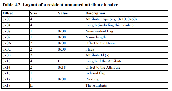
Figure 5 – MFT attribute header structure.
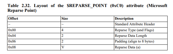
Figure 6 – $REPARSE_POINT attribute payload structure.
Our parsing effort with the structures listed above yields the following data:
A few important notes:
- We didn't find any public documentation for Microsoft's reparse data structure, but it wasn't too difficult to reverse-engineer.
- The reparse tag
0x90001018is defined here asIO_REPARSE_TAG_WCI_1with the next description:
| "Used by the Windows Container Isolation filter. Server-side interpretation only, not meaningful over the wire." |
- While reverse-engineering Windows modules in this research, several times we came across the referenced GUID
77 F6 64 82 B0 40 A5 4C BF 9A 94 4A C2 DA 80 87as a hardcoded value. This value indicates a reference to the host base layer, which we talk about it later. - The path in the reparse data shows the relative path of our sample file:
Windows\System32\kernel32.dll
Based on the above information, we can conclude that files are "linked" by the underlying file system (probably to a designated FS filter), but many questions are still unanswered: how is the VHDx constructed, what is the purpose of other VHDx's, and what component is responsible for linking to the host files.
VHDx Layering
If we track Procmon logs during the sandbox creation, we notice a series of VHDx access attempts:
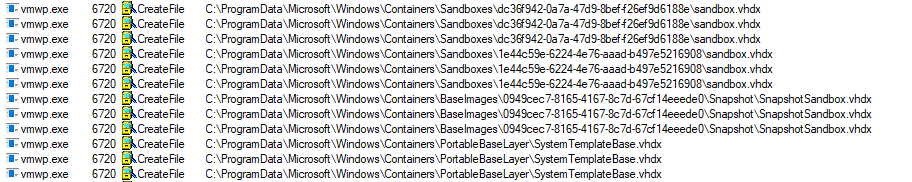
Figure 7 – VHDx layering lead.
While the first one is the "real" VHDx which we parsed previously, it is followed by 3 other VHDx accesses. We suspect that Microsoft used some sort of layering for the virtual disk templates.
Our theory is easily verified by inspecting the VHDx files using the binary editor:
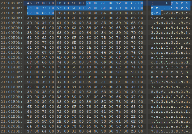
Figure 8 – parent_linkage tag in 010 Editor.
The parent locator in VHDx format can be given using multiple methods: absolute path, relative path, and volume path. The documentation can be found here.
With that knowledge, we can build the next layering:
Sandboxes\<new_sandbox_guid>\sandbox.vhdx– The "real" VHDx.Sandboxes\<constant_guid_per_installation>\sandbox.vhdx– Created once per sandbox install.BaseImages\0949cec7-8165-4167-8c7d-67cf14eeede0\Snapshot\SnapshotSandbox.vhdx– Probably relevant to the base layer snapshot.PortableBaseLayer\SystemTemplateBase.vhdx– Base template.
When we browse these virtual disks, we notice files are still missing; some system folders are empty, as well as folders for Users/Program Files and various other files.
Playing with Procmon leads us to understand that another important layer is missing: the OS base layer.
OS Base Layer
The OS base layer main file exists in the sandbox working folder in the next path: BaseImages\0949cec7-8165-4167-8c7d-67cf14eeede0\BaseLayer.vhdx. By looking at the installation process through Procmon, we can see that the next .wim (Windows Imaging Format) file, C:\Windows\Containers\serviced\WindowsDefenderApplicationGuard.wim, is extracted into the PortableBaseLayer folder by the same name, and is copied and renamed into the base layer file above. This shows yet another similarity between WDAG and Windows Sandbox.
When we browsed the BaseLayer.vhdx disk, we could see the complete structure of the created sandbox, but system files were still "physically" missing. Parsing the MFT record for kernel32.dll like we did previously results in the same $REPARSE_POINT attribute but with a different tag: 0xA0001027: IO_REPARSE_TAG_WCI_LINK_1. Remember this tag for later.
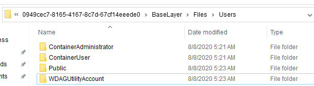
Figure 9 – Base layer user folders.
In addition, when we run mountvol command, we see that the base layer VHDx is mounted to the same directory where it exists:
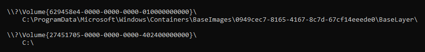
Figure 10 – Mounted OS base layer.
The service in charge of mounting that volume, and all previous functionality we mentioned up to this point, is the Container Manager Service CmService.dll.
This service runs an executable named cmimageworker.exe, with one of the next command line parameters, expandpbl/deploy/clean, to perform these actions.
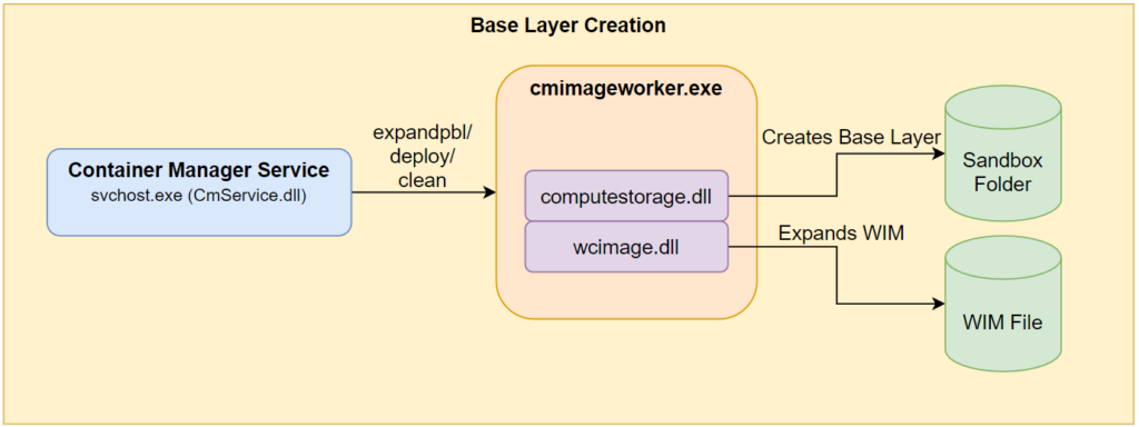
Figure 11 – CmService base layer creation.
We can observe the call to computestorage!HcsSetupBaseOSLayer in cmimageworker.exe, and part of the actual creation of the base layer in computestorage.dll.
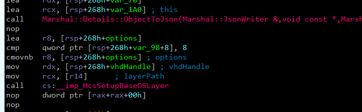
Figure 12 – cmimageworker!Container::Manager::Hcs::ProcessImage initiates base layer creation.
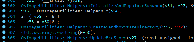
Figure 13 – Part of the base layer creation in computestorage!OsImageUtilities::ProcessOsLayer.
Microsoft issued the following statement regarding the sandbox:
| Part of Windows – everything required for this feature ships with Windows 10 Pro and Enterprise. No need to download a VHD! |
So far, we understand crucial implementation details regarding that feature. Let's continue to see how the container is executed.
Running the Sandbox
Running the Windows Sandbox application triggers an execution flow which we won't elaborate on here. We just mention that the flow leads to CmService executing vmcompute!HcsRpc_CreateSystem through an RPC call. Another crucial service, vmcompute.exe, runs and orchestrates all compute systems (containers) on the host.
In our case, the CreateSystem command also receives the next configuration JSON which describes the desired machine:
Note – The JSON is cut for readability. You can access the full JSON in Appendix A.
This JSON is created at CmService!Container::Manager::Hcs::Details::GenerateCreateComputeSystemJson. We didn't manage to track any file which helps build that configuration.
Before we start analyzing the interesting fields in the JSON, we want to mention this article by Palo Alto Networks. The article explains the container internals, and how Job and Silo objects are related.
The first interesting configuration tag is RunInSilo. This tag triggers a code flow in vmcompute which leads us to the next stack trace:
From the stack, we can understand that whenever the compute system receives the silo configuration, it creates and configures a container through a container!WcCreateContainer call. As part of its configuration, it also communicates with the wcifs.sys driver through FLTLIB!FilterSendMessage. We explain this driver and its purpose shortly.
The second interesting feature is the VirtualSmb tag for creating the respective shares for the mounted base layer path we mentioned previously. We'll get back to this shortly as well.
Container Isolation
As we can see in the stack trace, the container creation includes opening the filter communication channel on port \WcifsPort with the wcifs.sys driver, Windows Container Isolation FS Filter Driver. This is a common method for a user mode code to communicate with filter drivers.
This mini-filter driver has an important part in the implementation of the container filesystem virtualization. This driver fills this role in both the guest and the host.
File system filter drivers are usually quite complex, and this one isn't an exception. Luckily, James Forshaw of Google Project Zero recently wrote a great article which explains the low-level design of Windows FS filter drivers, which helps us understand the logic in our case.
We can divide the driver logic into 2 parts:
- Driver configuration – The configuration depends on whether the driver runs on the guest or on the host system.
- Handling the operation callbacks, such as
WcPreCreate,WcPostCreate,WcPreRead, andWcPostRead. These callbacks contain the main logic, data manipulation and proper redirections.
We'll explain some of the methods this driver uses to understand the ecosystem of the sandbox.
Initial Configuration
Guest Configuration
As we said previously, both the host, and the guest use this driver but in different ways.
The guest receives a set of parameters via the registry for its initial configuration. Some of these params are at HKLM\SYSTEM\CurrentControlSet\Control and HKLM\SYSTEM\CurrentControlSet\Control\BootContainer as we can see below:
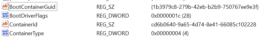
Figure 14 – HKLM\SYSTEM\CurrentControlSet\Control config values.
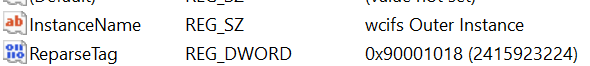
Figure 15 – HKLM\SYSTEM\CurrentControlSet\Control\BootContainer config values.
You might notice the IO_REPARSE_TAG_WCI_1 (code 0x90001018), which we saw earlier in the "real" VHDx file. This tag, together with IO_REPARSE_TAG_WCI_LINK_1, which we saw as a reparse tag in BaseLayer.vhdx, are hardcoded into the wcifs!WcSetBootConfiguration method:
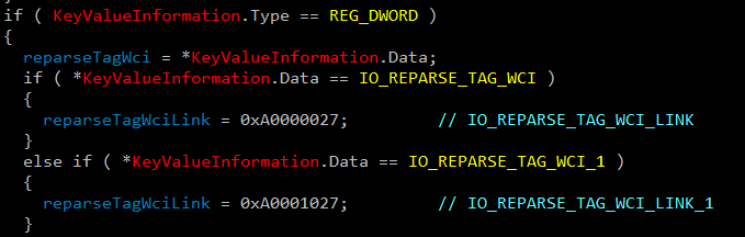
Figure 16 – Hardcoded reparse tag values in WcSetBootConfiguration.
The second, more important part of the guest configuration is in wcifs!WcSetupVsmbUnionContext, where it sets up a virtualized layer known as a Union Context. Behind the scenes, the driver stores customized data on several context objects and accesses them with the proper NT API – FltGetInstanceContext, PsGetSiloContext, and FltGetFileContext. These custom objects contain AVL trees and hash tables to efficiently look up the virtualized layers.
The WcSetupVsmbUnionContext method has two more interesting artifacts. One is a vSMB path which is part of the layer, and another is the HOST_LAYER_ID GUID which we saw previously in the parsed MFT and in the JSON that describes the virtual machine:

Figure 17 – Hardcoded vSMB path in WcSetupVsmbUnionContext.

Figure 18 – Hardcoded GUID for HOST_LAYER_ID.
As we delve deeper, we see signs that a Virtual SMB method is used to share files between the guest and the host. Soon we'll see that vSMB is the main method for the base layer implementation and mapped folder sharing.
Host Configuration
For the host system, the main configuration happens when the parent compute process, vmcompute, initiates the container creation, and sends a custom message to \WcifsPort. This triggers wcifs!WcPortMessage which is a callback routine for any message sent to that specific port.
Below is a partial reconstruction of the message sent by the service to the filter driver:
The ContextData field also contains the device paths the union should map.
Operation Callbacks
During the registration, the filter driver supplies a set of callbacks for each operation it wants to intercept. The filter manager invokes these callbacks pre/post each file operation, as we can see below.
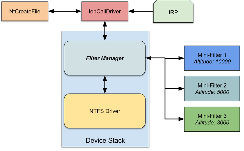
Figure 19 – Mini-filter architecture, courtesy of James Forshaw.
Without diving too much into the technical details, the driver defines and takes care of two custom reparse tags:
- IO_REPARSE_TAG_WCI_1 – This is the main tag that indicates the file instance on the disk is virtual, and the real path can be found in its internal structures. Example uses of this "conversion":
- The guest converts files from its native path
C:\Windows\system32\kernel32.dllto vSMB path\Device\vmsmb\VSMB-{dcc079ae-60ba-4d07-847c-3493609c0870}\os\Windows\System32\kernel32.dll. - The host converts files from the base layer device path
C:\ProgramData\Microsoft\Windows\Containers\BaseImages\0949cec7-8165-4167-8c7d-67cf14eeede0\BaseLayer\Files\Windows\System32\en-US\apphelp.dll.muito the real pathC:\Windows\System32\en-US\apphelp.dll.mui.
This conversion is quite interesting, as it happens mainly in empty system folders in the base layer which contain this reparse tag (like theen-USfolder).
- The guest converts files from its native path
- IO_REPARSE_TAG_WCI_LINK_1 – This tag is used only on the host as far as we could tell, and links the system files from the base layer device path
C:\ProgramData\Microsoft\Windows\Containers\BaseImages\0949cec7-8165-4167-8c7d-67cf14eeede0\BaseLayer\Files\Windows\System32\kernel32.dllto the real pathC:\Windows\System32\kernel32.dll. Compared to the previous point, this example DLL file entry does exist in the base layer, and has this reparse tag.
The discovery that vSMB is the primary method for the OS base layer sharing was quite surprising. Now that we know it is a crucial communication method in the ecosystem the natural next step is to dig further inside.
(v)SMB File Sharing
During the sandbox installation, we noticed vmcompute creates several virtual shares by invoking CreateFileW to the storage provider device, and sends IOCTL 0x240328. A sample path for such an invoke might look like this: \??\STORVSP\VSMB\??\C:\ProgramData\Microsoft\Windows\Containers\BaseImages\0949cec7-8165-4167-8c7d-67cf14eeede0\BaseLayer\Files.
The method that creates these shares is vmcompute!ComputeService::Storage::OpenVsmbRootShare. We can see its flow in the next stack trace:
In addition, when we map host folders to the guest using the WSB file configuration, the same method is called. For example, mapping the Sysinternals folder results in the next call to the driver: \??\STORVSP\VSMB\??\C:\Users\hyperv-root\Desktop\SysinternalsSuite.
Accessing Files via (v)SMB
After creating these shares, we can access them within the guest through the created alias. We can use the type command to print the kernel32.dll of the host with the next path \\.\vmsmb\VSMB-{dcc079ae-60ba-4d07-847c-3493609c0870}\os\Windows\System32\kernel32.dll:
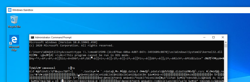
Figure 20 – Accessing the vSMB share.
To serve the vSMB files, the vmusrv module, which is part of the VM worker process, creates a worker thread. This module is a user mode vSMB server which requests packets directly from the VMBus at the vmusrv!VSmbpWorkerRecvLoop routine, and then proceeds to process the packets.
Serving Create File Operation
Whenever vmusrv receives a Create SMB request, it initiates a new request to the storage provider driver. Such a call might look like this:
The communication with the storage provider is done through an IOCTL with the code 0x240320, while the referenced handle is the vSMB path opened on the initialization phase:
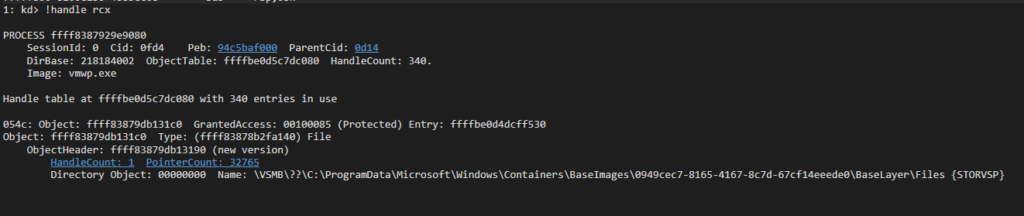
Figure 21 – The handle in which the IOCTL is referred.
If we look closely at storvsp!VspVsmbCommonRelativeCreate, we see that every execution is followed by a call to nt!IoCreateFileEx. This call contains the relative path of the desired file with an additional RootDirectory field which represents the \Files folder in the mounted base layer VHDx:
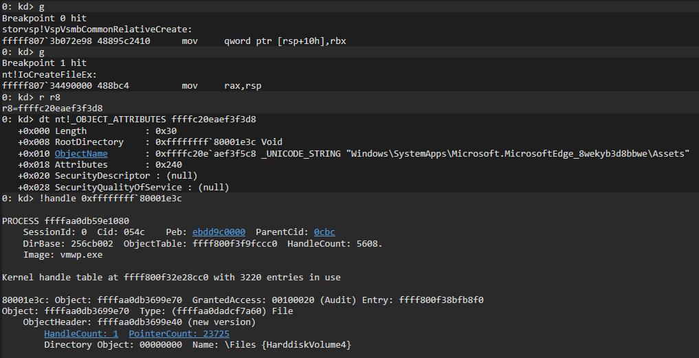
Figure 22 – Execution of IoCrateFileEx by storvsp.sys.
Serving Read/Write Operation
Read/Write operations are executed by the worker thread in vmusrv!CFSObject::Read/vmusrv!CFSObject::Write. If the file is small enough, the thread simply executes ReadFile/WriteFile on the handle. Otherwise it maps the file to the memory, and transfers it efficiently through RDMA on top of VMBus. This transfer is executed at vmusrv!SrvConnectionExecuteRdmaTransfer, while the RDMA communication is done with the RootVMBus device (host VMBus device name) using IOCTL 0x3EC0D3 or 0x3EC08C.
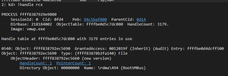
Figure 23 – Communication with \Device\RootVmBus\rdma\494 for the read/write operation.
Guest-to-Host Flow
Based on a few insights from this article explaining the Storvsc.sys/Storvsp.sys relationship, we can combine all previous technical blocks to the next file access flow.
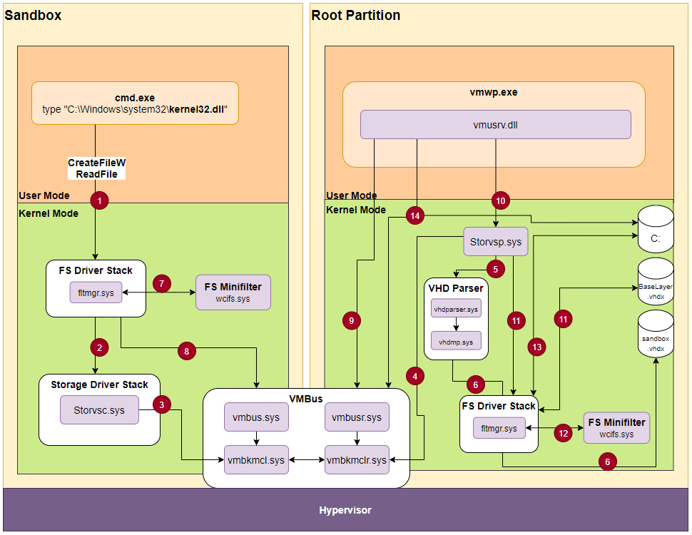
Figure 24 – File access flow.
- We use the command
typeto open and print the content of thekernel32.dllfile. This is a system file, and therefore the sandbox doesn't own its copy, but uses the host's copy. - The guest is not aware that the file doesn't exist, so it performs a normal file access through the filesystem driver stack up to the storage driver stack.
- The Hyper-V storage consumer
Storvsc.sysis a miniport driver, meaning it acts as the virtual storage for the guest. It receives and forwards SCSI requests over the VMBus. - The storage provider
Storvsp.syshas a worker thread listening for new messages over the VMBus atstorvsp!VspPvtKmclProcessingComplete. - The provider parses the VMBus request, and passes it to
vhdparser!NVhdParserExecuteScsiRequestDisk, which executesvhdmp.sys, the VHD parser driver. - Eventually,
vhdmp.sysaccesses the physical instance ofsandbox.vhdxthrough the filter manager, and performs read/write operation. In this case, it reads the data requested by the guest filesystem filter manager. That data is returned to the filter manager for further analysis. - As explained previously, the returned entry is tagged with a WCI reparse tag and with the host layer GUID. When
wcifs.sysexecutes its post-create operation on the file, it looks for the union context for that device, and replaces the file object with the next one:\Device\vmsmb\VSMB-{dcc079ae-60ba-4d07-847c-3493609c0870}\os\Windows\System32\kernel32.dll - The
\Device\vmsmbdevice was created as an SMB share, so the filter manager accesses it like any other normal share. Behind the scenes, it performs SMB requests over VMBus to the host. - The vSMB user-mode server
vmusrv.dllpolls the\\.\VMbus\device for new messages in its worker thread methodvmusrv!SmbWorkerThread. - As we showed previously, in a create operation, the server communicates with the storage provider through IOCTL on the handle of mounted OS base layer:
\Device\STORVSP\VSMB\??\C:\ProgramData\Microsoft\Windows\Containers\BaseImages\0949cec7-8165-4167-8c7d-67cf14eeede0\BaseLayer\Files - The storage provider executes the file request through
IoCreateFileEx. That request is relative, and contains theRootDirectoryof the mounted OS layer. This triggers the filter manager to open the file in the mounted OS layer. - Similar to step (7), the returned entry contains a WCI reparse tag, which causes
wcifs.systo change the file object in the post-create method. It changes the file object to its physical path:C:\Windows\System32\kernel32.dll - Access the host
kernel32.dllfile, and return back to the guest. - For a
ReadFileoperation, thewcifs.sysdriver saves a context state on top of the file object to help it perform a read/write operation. In addition, the worker threadvmusrvexecutes the read request either with direct access to the file, or through RDMA on top VMBus.
The actual process is much more complex, so we tried to focus on the components crucial to the virtualization.
The sandbox also allows mapping folders from host to guest through its configuration. Such folders receive a unique alias for the vSMB path, and the access is similar to the OS layer. The only difference is that the path is altered in the guest filter manager by bindflt.sys.
For example, if we map the SysinternalsSuite folder to the guest Desktop folder, the path C:\Users\WDAGUtilityAccount\Desktop\SysinternalsSuite\Procmon.exe is altered into \Device\vmsmb\VSMB-{dcc079ae-60ba-4d07-847c-3493609c0870}\db64085bcd96aab59430e21d1b386e1b37b53a7194240ce5e3c25a7636076b67\Procmon.exe, which leaves rest of the process the same.
Playing with the Sandbox
One of our targets in this research was to modify the base layer content according to our needs. Now that we understand the ecosystem, it appears to be quite easy.
The modification has a few simple steps:
- Stop
CmService, the service that creates and maintains the base layer. When the service is unloaded, it also removes the base layer mounting. - Mount the base layer (it is in the
C:\ProgramData\Microsoft\Windows\Containers\BaseImages\0949cec7-8165-4167-8c7d-67cf14eeede0\BaseLayer.vhdxfile). This can be done by double clicking, or using thediskmgmt.mscutility. - Make modifications to the base layer. In our case, we added all FLARE post-installation files.
- Unmount the base layer.
- Start
CmService.
The moment we start the sandbox, we have our awesome FLARE VM!
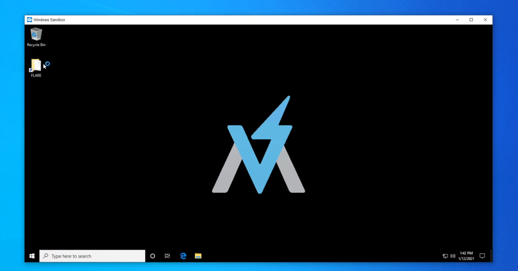
Figure 25 – FLARE VM on top of the Windows Sandbox.
Summary
When we started researching Windows Sandbox, we had no idea that such a "simple" operation boils down to a complex flow with several Microsoft internal undocumented technologies such as vSMB and Container Isolation.
We hope this article will help the community with further information gathering and bug hunting. For us, this was a big first step into researching and understanding virtualization related technologies.
For any technical feedback, feel free to reach out on twitter.
Links
Hyper-V VmSwitch RCE Vulnerability
https://www.youtube.com/watch?v=025r8_TrV8I
Windows Sandbox
https://techcommunity.microsoft.com/t5/windows-kernel-internals/windows-sandbox/ba-p/301849
Windows Sandbox WSB Configuration
Windows Containers
- https://docs.microsoft.com/en-us/virtualization/windowscontainers/about/
- https://unit42.paloaltonetworks.com/what-i-learned-from-reverse-engineering-windows-containers/
NTFS Attributes
https://www.urtech.ca/2017/11/solved-all-ntfs-attributes-defined/
Reparse Point
https://docs.microsoft.com/en-us/windows/win32/fileio/reparse-points
NTFS Documentation
https://dubeyko.com/development/FileSystems/NTFS/ntfsdoc.pdf
NTFS Reparse Tags
VHDx Parent Locator
FS Filter Driver – Communication between User Mode and Kernel Mode
Hunting for Bugs in Windows Mini-Filter Drivers
https://googleprojectzero.blogspot.com/2021/01/hunting-for-bugs-in-windows-mini-filter.html
Hyper-V Storvsp.sys-Strovsc.sys Flow
https://www.linkedin.com/pulse/hyper-v-architecture-internals-pravin-gawale/
RDMA Explained by Microsoft
Appendix A
Windows Sandbox JSON configuration for vmwp